Converter bridge circuit diagram power high seekic Single phase half bridge inverter explained [solved] only problem 2! repeat problem 1 for the full-wave bridge
Simple AC to DC converter using bridge rectifier
Circuit power bridge converter supply seekic Full-bridge converter electrical schematic diagram Simple ac to dc converter using bridge rectifier
Bridge circuit converter gr next above size click
Ir2110 mosfet driver circuit diagramConverter bridge diagram schematic electrical seekic circuit Dc voltage doubler and voltage multiplier circuits workingInverter waveforms controlled.
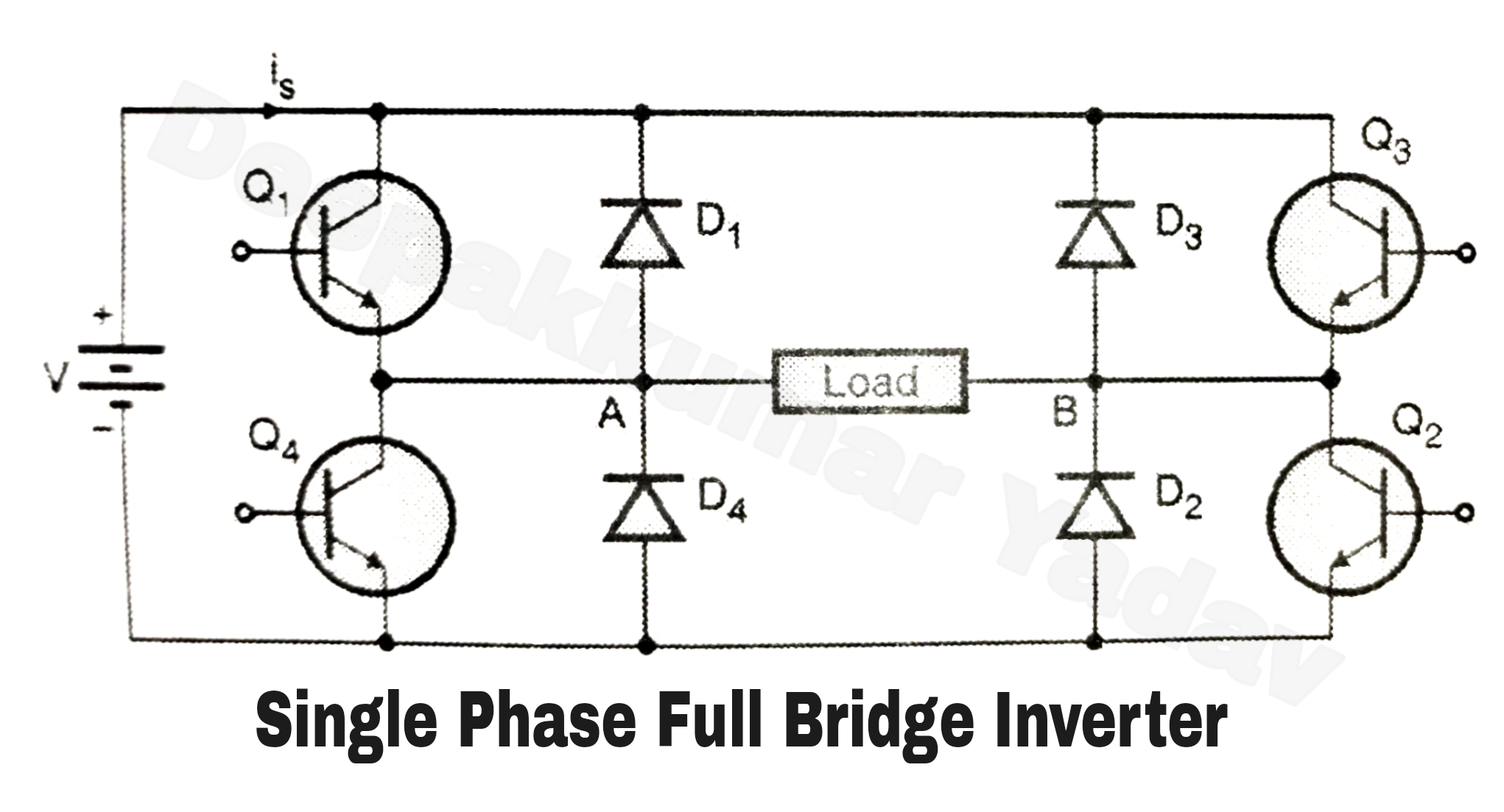
Single phase full bridge inverter (square wave output)(a) ir2110 circuit, (b) full-bridge circuit the ir2110/ir2113 are high Inverter output resistive inductiveSchematic diagram of half bridge converter circuit.

High-power full-bridge converter circuit diagram
Full bridge converter circuit under repository-circuits -49490- : next.grRectifier converter circuit Ir2110 circuits mosfet decouplingInverter electricalbaba.
Rectifier capacitor resistor transcription electricalSingle phase full bridge inverter explained Bridge converter diagram schematic electrical circuit seekic communication typical waveformFull-bridge converter electrical schematic diagram.

Doubler multiplier 120v eleccircuit circuits
Full bridge inverter .
.

[Solved] Only problem 2! Repeat Problem 1 for the full-wave bridge

Ir2110 Mosfet Driver Circuit Diagram - peerpowerup

Index 91 - power supply circuit - Circuit Diagram - SeekIC.com

Full Bridge Inverter - Circuit, Operation, Waveforms & Uses

High-power full-bridge converter circuit diagram - Power_Supply_Circuit

Full-Bridge converter electrical schematic diagram - Communication

Single Phase Half Bridge Inverter Explained - Electrical Concepts

Single Phase Full Bridge Inverter (Square Wave Output)

Full-Bridge converter electrical schematic diagram - Communication