A novel high frequency inverter 13+ high frequency inverter circuit diagram 5kva ferrite core inverter circuit
Designing 1kW Sine Wave Inverter Circuit | PCB Design Full Guide
Simple 3 phase inverter circuit Inverter circuit sine wave diagram board schematic solar power projects electronics arduino inverters using 1000w diy ic 50hz charger square Inverter circuit diagram dc 12v to ac 220v 200w sine wave
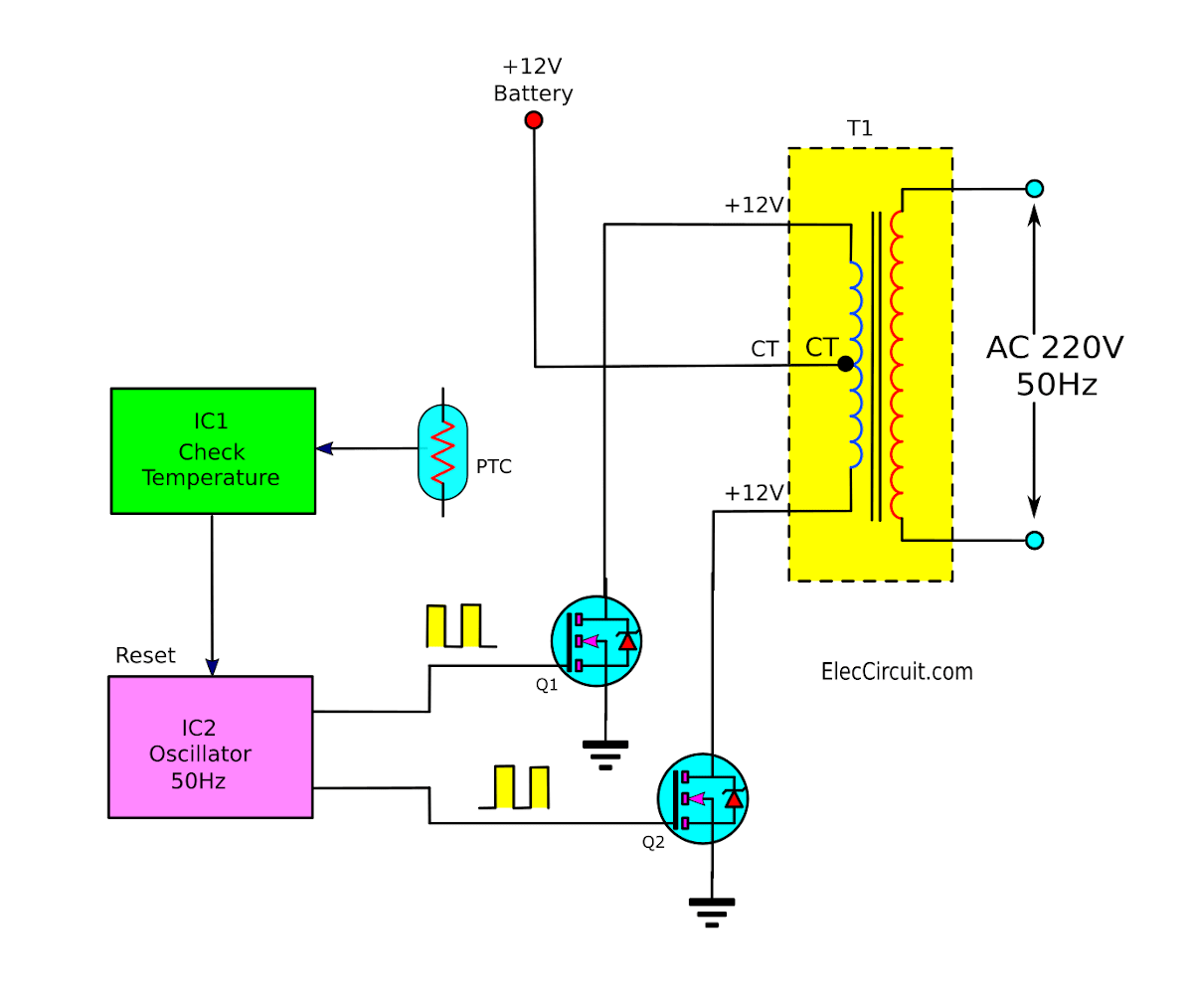
Diagram block inverter watt inverters 200watt operation circuits control electronic eleccircuit output projects transistors two figure
Inverter sine wave circuit pure simple diagram battery wiring watt inverters power homemade circuits electronic modified above detailsInverter parasitic topology Three phase inverter circuit diagramInverter diagram 12v circuit dc ac 220v wave sine 200w schematic schematics diagrams gif.
Single phase pure sine wave inverter using arduinoInverter smps frequency improved based high factor power figure Designing 1kw sine wave inverter circuitThe topology of high-frequency inverter with parasitic elements.

Inverter sine microcontrollerslab inspirasi pwm
Microtek digital inverter circuit diagramInverter voltage wave circuit diagram Inverter circuit diagram using 555 timerSimple pure sine wave inverter circuit.
Inverter mosfet ne555 simple eleccircuit sine volts voltage 50hz sg3524 schematics amplifier transformer wiring figure1Operation of 200 watt inverter diagram Inverter frequency high diagram circuit power 500w sourceHigh frequency smps based inverter with improved power factor.

Inverter phase circuit three 120 degree conduction mode diagram dc dilip raja nov
Inverter circuit diagram 5kva pwm core ferrite sinewave homemade sine circuits board solar using working transformer calculation details choose systemPhase inverter circuit simple homemade circuits make three using driver arduino solar bridge ic projects electronics stage battery artikel automatic Inverter voltage circuit diagram wave simple projectInverter circuit diagram microtek digital pcb layout complete following link click power.
.

13+ High Frequency Inverter Circuit Diagram | Robhosking Diagram

single phase pure sine wave inverter using arduino

Simple 3 Phase Inverter Circuit - Homemade Circuit Projects
Inverter Circuit Diagram Using 555 Timer - Home Wiring Diagram

Operation of 200 watt inverter diagram | ElecCircuit.com

Simple Pure Sine Wave Inverter Circuit - 500 Watt Pure Sine

Inverter Voltage Wave Circuit Diagram | Electronic Circuits Diagram

The topology of high-frequency inverter with parasitic elements

5kva Ferrite Core Inverter Circuit - Full Working Diagram with